By Bartek Moczulski, Consulting System Engineer, Fortinet Inc.
This tutorial shows you how to use Terraform to deploy a FortiGate reference architecture to help protect your applications against cyberattacks. FortiGate is a next-generation firewall (NGFW) with software-defined wide area network (SD-WAN) capabilities deployed as a network virtual appliance in Compute Engine. When deployed, FortiGate can help secure applications by inspecting all inbound traffic originating from the internet and outbound and internal traffic between application tiers. You can use the same FortiGate cluster as a secure web gateway to protect outbound traffic originating from your workloads.
In this tutorial, you create several networks and deploy a high-availability (HA) FortiGate cluster. You also create a two-tier web application and configure FortiGate and Google Cloud to help enable secure inbound traffic, outbound traffic, and internal traffic.
Architecture
The following diagram shows that the architecture deployed in this tutorial consists of an HA cluster of FortiGate NGFWs that uses a pair of external and internal load balancers to direct traffic to the active FortiGate VM instance. A two-tier web application is deployed behind the NGFWs. Connections from the internet to the application frontend (Tier 1) pass through the active FortiGate instance, as indicated by the red path. The NGFWs also inspect connections from Tier1 to Tier2, as indicated by the purple path.
For more information about testing NGFW connectivity and testing threat prevention, see Verify the FortiGate NGFW deployment.

Create a custom role and a service account
FortiGate instances can query Google API Client Libraries to resolve dynamic addresses in a firewall policy. This popular functionality lets you build firewall policies based on network tags and other metadata rather than on static IP addresses. In this section, you create an IAM role and a service account with the minimum required privilege set, and a binding policy.
After you create roles, they can't be deleted and recreated.
In Cloud Shell, create a Fortinet IAM role:
GCP_PROJECT_ID=$(gcloud config get-value project)

gcloud iam roles create FortigateSdnReader --project=$Google Cloud_PROJECT_ID \
  --title="FortiGate SDN Connector Role (read-only)" \
  --permissions="compute.zones.list,compute.instances.list,container.clusters.list,container.nodes.list,container.pods.list,container.services.list"
Create a Fortinet service account:
GCP_PROJECT_ID=$(gcloud config get-value project)

gcloud iam roles create FortigateSdnReader --project=$GCP_PROJECT_ID \
  --title="FortiGate SDN Connector Role (read-only)" \
  --permissions="compute.zones.list,compute.instances.list,container.clusters.list,container.nodes.list,container.pods.list,container.services.list"

gcloud iam service-accounts create fortigatesdn-ro \
  --display-name="FortiGate SDN Connector"
Create a binding policy:
gcloud projects add-iam-policy-binding $GCP_PROJECT_ID \
  --member="serviceAccount:fortigatesdn-ro@$GCP_PROJECT_ID." \
  --role="projects/$GCP_PROJECT_ID/roles/FortigateSdnReader"
Initialize Terraform
In this section, you modify the files in the Day0 directory in the
Terraform GitHub repository:
Before you begin, find the public IP address of your computer by searching for My IP address.
In Cloud Shell, update the
terraform.tfvarsfile with your Google Cloud project ID and theus-central1region:GCP_PROJECT = PROJECT_ID GCE_REGION = us-central1 Prefix = fgt-
Add your public IP address to the
admin_acllist in themain.tffile:module "fortigates" { source = "../modules/fgcp-ha-ap-lb" region = var.GCE_REGION service_account = data.google_service_account.fgt.email != null ? data.google_service_account.fgt.email : "" admin_acl = ["IP-ADDRESS", "${data.http.my_ip.body}/32"] api_acl = ["${data.http.my_ip.body}/32"]This template restricts access for the administrative interface and FortiGate API to the IP address that you run the template from.
Initialize Terraform:
terraform init
terraform plan -out tf.plan
## verify the list of resources that will be created before moving to the next step.

terraform apply tf.plan
To connect to the primary FortiGate instance, use
sshwith the default user ID:admin.The default password and primary IP address are visible in the Terraform output. When you connect for the first time, you must change the admin password.
Verify the status of the provisioning by checking the output of the following command:
get system ha statusThe output should resemble the data in the following screenshot:
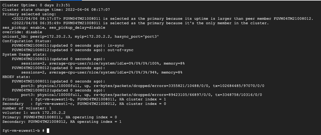
At the end of the output, you should see two instances:
PrimaryandSecondary. This output confirms that both instances were properly licensed and successfully formed an HA cluster.
This section described the minimal deployment of a FortiGate cluster. In the next section, you add additional functionality such as routes, firewall policies, and peered VPCs.
Deploy FortiGate NGFW workloads
In this section, you update the files in the Day1 directory of the
GitHub repository
to deploy workloads with a new public IP address. You also update the
configuration files of the FortiGate NGFW.
The Day1 directory contains the following files:
day0-import.tf: Imports data from theday0deployment to identify FortiGate instances and their API key. It also indicates where the Terraform state file is pulled from.workloads.tf: Creates a proxy and web servers into new Tier 1 and Tier 2 VPC networks.main.tf: Connects Tier 1 and Tier 2 VPC networks with internal VPC of the FortiGate cluster. It also enables inbound and outbound connectivity and adds Tier 1 to the Tier 2 east-west firewall policy.
Using the -parallelism=1 Terraform option in the code sample helps reduce or
remove concurrency issues related to
Google Cloud peering
and routing operations for multiple VPC networks in a single Terraform
deployment.
In Cloud Shell, access the
Day1directory:cd ../day1To deploy a sample web application and configure FortiGate to forward connections to it, run the following commands:
terraform init
terraform plan -out day1.plan
terraform apply day1.plan -parallelism=1
The following screenshot shows a
route operation in progresserror. An error like this can occur if you don't use the-parallelismflag. Without this flag, you might run into concurrency issues.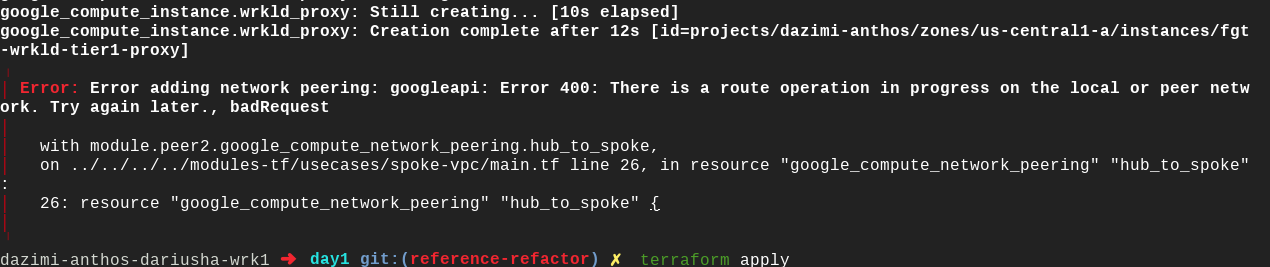
To recover from this error, run the
terraform applycommand again. Terraform automatically verifies which steps failed and adds the missing resources.
Verify the FortiGate NGFW deployment
At this point in the tutorial, you've deployed a multi-tier architecture with inbound, outbound, and internal connectivity, all secured using FortiGate. In this section, you verify your deployment of the FortiGate NGFW. You also attempt to upload a harmless virus file to ensure that the firewall is operating. To connect to the web server over FortiGate, check the public IP address of the external load balancer in Terraform outputs. Connect to it using your web browser.
Wait a minute or two for the proxy and web server provisioning to finish before attempting the following verification steps:
- In Cloud Shell, copy the public IP address of the external
load balancer from the
public_ipoutput of theterraform applycommand. - Launch a web browser.
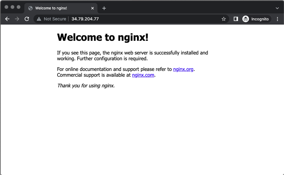
Connect to the public IP address of the load balancer:
http://Public IP address of the load balancer
You should see the default Nginx welcome page.
To download a harmless test virus file from the European Institute for Computer Anti-Virus Research, and to verify that FortiGate NGFW threat inspection is working, add
/eicar.comto the IP address you entered in the previous step.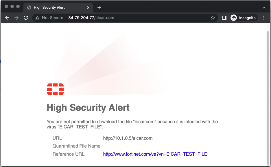
To see more details about the inspected network traffic:
- In the web browser, enter the public IP address of the first FortiGate instance (the same IP address you used earlier for SSH connections) into the address bar.
- Connect to the FortiGate web console using a web browser. The HTTPS console is available on the standard port of 443 by default.
Skip the following optional setup steps:
- Dashboard configuration
- Firmware updates
- Initial welcome video
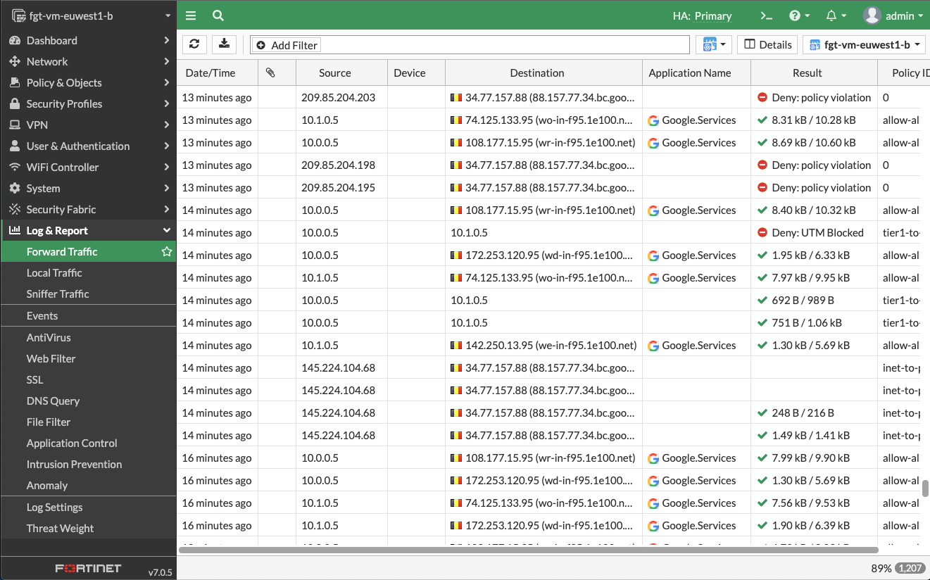
Select Log & Report > Forward Traffic from the FortiGate web console.
A list of all the connections attempted through the FortiGate firewall appears. You should be able to identify the following:
- Successful connection from your own IP address to the web server followed by a successful internal connection.
- Multiple outbound connections with various applications detected.
- Another internal connection between
10.0.0.5and10.1.0.5that is blocked because of UTM policy. This action proves that the east-west threat inspection is working correctly.
To reveal details of the detected threat, double-click on the blocked connection in the Result column. A details page appears.
Select Security. Security appears in Log details.