Spanner Graph lets you model connected data as a property graph that represents information as a network of nodes and edges. Nodes symbolize entities, and edges show connections between them. Nodes and edges include labels that classify the types of nodes and edges. Nodes and edges also include properties that describe them.
You define a Spanner Graph schema by mapping rows from input tables to graph nodes and edges. Customize labels and properties for nodes and edges, and understand how schema changes affect graph dependencies. You can also manage schemaless data for more flexible graph definitions.
To learn more about Spanner Graph, see the Spanner Graph overview.
Understand the property graph data model
A property graph lets you model connected data. It represents information as a network of nodes and edges. Nodes symbolize entities in your data landscape, such as customers, products, or locations. Edges show the connections between those nodes, capturing relationships such as purchased, follows, or located-in.
Both nodes and edges can include the following information:
Labels: Classify nodes and edge types. If you don't explicitly define a label for a node or an edge, Spanner Graph uses the input table name as the default label. For example,
Accountcould be a label.Properties: Used to describe nodes and edges. For example, a
Personnode might have anameproperty with the valueAlexand anidproperty with the value1.
The example in Figure 1 shows how you might design a graph to model financial activities. This graph includes the following types of entities modeled as nodes:
- Person: Represents an individual involved in financial transactions.
- Account: Represents a bank account used for transactions.
These entities are connected by different types of relationships, which are represented by the following directed edges:
- Owns: A person owns one or more accounts.
- Transfers: Money moves from one account to another.
Each directed edge indicates a one-way relationship that flows from a source
node to a destination node. For example, a Transfers edge connects a source
Account to a destination Account, indicating the flow of money.
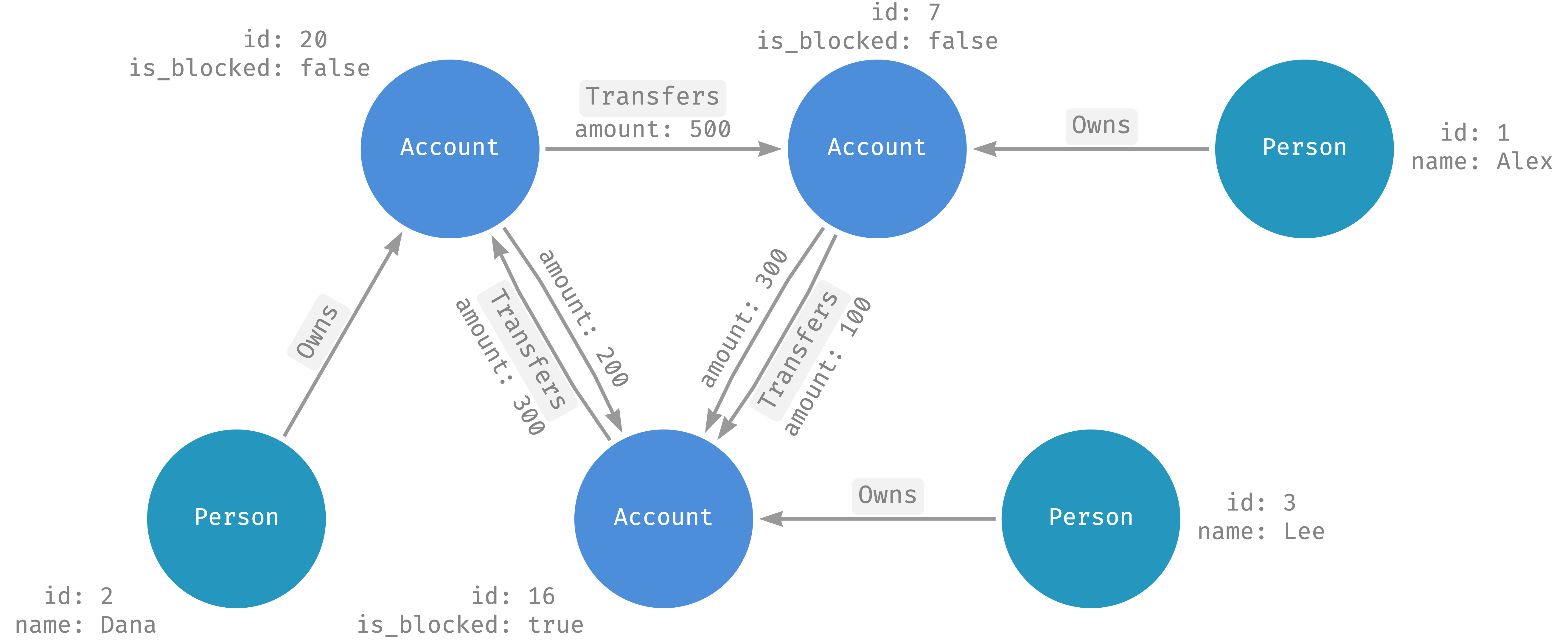
Figure 1. Example graph with multiple nodes and directed edges.
Nodes and edges include additional information in properties.
- Person nodes include these properties:
name(STRING)id(INT64)
- Transfers edges include this property:
amount(FLOAT64)
Directed and undirected edges
The example graph uses directed edges that indicate a specific direction in the relationship between entities. However, some relationships, like the friend relationship in a social network, are undirected and represent a reciprocal connection without a distinct origin or endpoint. In this case, you can model undirected edges as two directed edges, one edge in each direction.
Spanner Graph schema design
Spanner Graph lets you use the CREATE PROPERTY GRAPH statement to create a graph from tables. The tables that create graphs are called input tables. This approach uses SQL/PGQ (Property Graph Queries), which is part of SQL:2023 Standards.
Define a node from a table
To define a node, add a node definition in the NODE TABLES clause. The simplest form of node definition contains only an input table name. Spanner Graph maps rows from the input table to graph nodes.
In the following example, you use the
NODE TABLES
clause to define the Account node in the FinGraph property graph. The node
definition contains the input table Account.
-- First, create an Account table.
CREATE TABLE Account (
  id           INT64 NOT NULL,
  create_time  TIMESTAMP,
) PRIMARY KEY (id);

-- Next, use the Account table as input table of Account node definition.
CREATE PROPERTY GRAPH FinGraph
  NODE TABLES (
    Account
  );
Default labels and properties
In addition to using the input table name as the default label, Spanner Graph exposes all columns from the input table as node properties.
In the previous example,
- Each account node uses the
Accountlabel. - Each account node includes
[id, create_time]properties from theAccounttable columns.
Element key
A node definition also defines the element key that uniquely identifies a graph node.
- By default, the element key is the primary key of the input table.
- You can use the
KEYclause to explicitly define element keys. - You can use columns with a unique index constraint as element keys.
The following example defines Account node and Person node.
- The
Accountnode uses theAccounttable's primary key as its element key by default. - The
Personnode, on the other hand, explicitly specifies theidas the element key with theKEYclause.
CREATE TABLE Person (
  id           INT64 NOT NULL,
  name         STRING(MAX),
) PRIMARY KEY (id);

CREATE TABLE Account (
  id           INT64 NOT NULL,
  create_time  TIMESTAMP,
) PRIMARY KEY (id);

CREATE PROPERTY GRAPH FinGraph
  NODE TABLES (
    Person KEY (id),
    Account
  );
Map a row in the input table to a node in the graph
- Each row with a non-null element key maps to a unique node in the graph, identified by the element key.
- Rows with a null element key are ignored.
Define an edge from a table
To define an edge, add an edge definition into the EDGE TABLES clause. The simplest form of edge definition contains only an input table name. Spanner Graph maps rows from the input table to graph edges.
The default label and properties of the edges are defined in the same way as nodes.
Each edge's element key is defined in the same way as nodes.
Source and destination node references
In the following example, you create a property graph FinGraph with the
following:
PersonandAccountnodesPersonOwnAccountedge
CREATE TABLE Person (
 id            INT64 NOT NULL,
 name          STRING(MAX),
) PRIMARY KEY (id);

CREATE TABLE Account (
 id            INT64 NOT NULL,
 create_time   TIMESTAMP,
) PRIMARY KEY (id);

CREATE TABLE PersonOwnAccount (
 id            INT64 NOT NULL,
 account_id    INT64 NOT NULL,
 create_time   TIMESTAMP,
 FOREIGN KEY (account_id) REFERENCES Account (id)
) PRIMARY KEY (id, account_id),
  INTERLEAVE IN PARENT Person;

CREATE PROPERTY GRAPH FinGraph
  NODE TABLES (
    Person,
    Account
  )
  EDGE TABLES (
    PersonOwnAccount
      SOURCE KEY (id) REFERENCES Person (id)
      DESTINATION KEY (account_id) REFERENCES Account (id)
  );
An edge definition defines the source and destination node reference by using
the SOURCE KEY, DESTINATION KEY, and REFERENCES clauses. The following
example uses the edge definition of PersonOwnAccount to illustrate this
concept:
EDGE TABLES (
  PersonOwnAccount
    SOURCE KEY (id) REFERENCES Person (id)
    DESTINATION KEY (account_id) REFERENCES Account (id)
)
Each PersonOwnAccount edge connects a Person (source) to an Account
(destination) node.
- The source node of an edge is a
Personnode where theidis the same as the edgeid. - The destination node of an edge is an
Accountnode where theidis the same as the edgeaccount_id.
Additionally, the following is true for the PersonOwnAccount edge:
- The element key is the primary key of the
PersonOwnAccounttable, namely(id, account_id). - Each edge has the same set of properties as the columns from the
PersonOwnAccounttable. - Each edge has the default
PersonOwnAccountlabel.
Map a row in an edge input table to edges in the graph
- Each row in the edge input table, where the element key is not null, usually maps to a unique edge in your graph.
- A row might correspond to zero or more than one edge in the graph. For example, this occurs when the source node reference matches zero or more nodes in the source node table.
Define nodes and edges within a single table
You can define a node and its incoming or outgoing edges in a single table if your table's columns define a relationship to another table. This approach reduces the number of tables, simplifies data management, and can improve query performance by eliminating the need for a join to a separate edge table.
For example, if the following Account table has a composite primary key
(owner_id, account_id), the owner_id part can be a foreign key that
references a Person table. This structure allows the Account table to
represent both the Account node and the incoming edge from the Person node.
  CREATE TABLE Person (
    id INT64 NOT NULL,
  ) PRIMARY KEY (id);

  -- Assume each account has exactly one owner.
  CREATE TABLE Account (
    owner_id INT64 NOT NULL,
    account_id INT64 NOT NULL,
    FOREIGN KEY (owner_id) REFERENCES Person(id)
  ) PRIMARY KEY (owner_id, account_id);
You can use the Account table to define both the Account node and its
incoming Owns edge. This is shown in the following CREATE PROPERTY GRAPH
statement. In the EDGE TABLES clause, you give the Account table the alias
Owns. This is because each element in the graph schema must have a unique
name.
  CREATE PROPERTY GRAPH FinGraph
    NODE TABLES (
      Person,
      Account
    )
    EDGE TABLES (
      Account AS Owns
        SOURCE KEY (owner_id) REFERENCES Person
        DESTINATION KEY (owner_id, account_id) REFERENCES Account
    );
Customize labels and properties
You can use the LABEL and PROPERTIES clauses to customize labels and properties.
The following example defines two nodes: Person and Account.
- The
Personnodes use theCustomerlabel to expose theaddressproperty. Theaddressproperty is defined by the expressionCONCAT(city, ", ", country),that refers to thecityandcountrycolumn from the input tablePerson. - For
Account, theAccountnode uses theAccountlabel to expose theidandcreate_timeproperties. PersonandAccounthave theEntitylabel with properties [id, name].- For
Person, theidandnameproperties come from the input table columns. - For
Account, thenameproperty refers to thenick_namecolumn of the input table.
- For
CREATE TABLE Person (
 id               INT64 NOT NULL,
 name             STRING(MAX),
 birthday         TIMESTAMP,
 country          STRING(MAX),
 city             STRING(MAX),
) PRIMARY KEY (id);

CREATE TABLE Account (
 id               INT64 NOT NULL,
 create_time      TIMESTAMP,
 is_blocked       BOOL,
 nick_name        STRING(MAX),
) PRIMARY KEY (id);

CREATE PROPERTY GRAPH FinGraph
  NODE TABLES (
    Person KEY (id)
      LABEL Customer
        PROPERTIES (CONCAT(city, ", ", country) AS address)
      LABEL Entity PROPERTIES (id, name),
    Account KEY (id)
      LABEL Account PROPERTIES (id, create_time)
      LABEL Entity PROPERTIES (id, nick_name AS name)
  );
Label and property consistency
In a graph, labels and properties are uniquely identified by their names. You can use labels and properties with the same name in multiple node or edge definitions. However, labels and properties with the same name must follow these rules:
- Properties with the same name use the same value type.
- Labels with the same name expose the same list of properties.
In the previous example, the Entity label is defined in both Person and
Account nodes. Both definitions include the same set of property names [id,
name] with identical value types.
Dependencies between graphs and other schema objects
The graph created by CREATE PROPERTY GRAPH depends on other schema objects,
such as the input tables of the node and edge definitions, and the table columns
referenced by the properties. Spanner Graph doesn't permit a schema
change that breaks one of these dependencies.
The following statement makes FinGraph dependent on the Account table and
the id and create_time columns.
CREATE OR REPLACE PROPERTY GRAPH FinGraph
  NODE TABLES (
    Account PROPERTIES (id, create_time)
  );
In this example, Spanner Graph doesn't permit the following schema changes:
- You can't drop the
Accounttable. To do this, you need to remove theAccountnode definition. For more information, see Remove existing nodes or edge definitions. - You can't drop
create_timecolumns from theAccounttable. To do this, you need to remove thecreate_timeproperty from theAccountnode definition. For more information, see Update existing nodes or edges definitions.
However, you can make the following schema changes:
- Modify the
Accounttable andidandcreate_timecolumns schema if other schema requirements permit it. For more information, see Make schema updates.
View a schema visualization
You can view a schema visualization in Spanner Studio after you run a Spanner Graph query. For more information, see Use Spanner Graph visualizations.
Manage schemaless data
Spanner Graph also supports schemaless data management that is helpful when you need a more flexible graph definition. For more information, see Manage schemaless data in Spanner Graph.
What's next
- Create a Spanner Graph schema.
- Update or delete a Spanner Graph schema.
- Manage schemaless data with Spanner Graph.