This page describes how Cloud TPU works with Google Kubernetes Engine (GKE), including terminology, the benefits of Tensor Processing Units (TPUs), and workload scheduling considerations. TPUs are Google's custom-developed, application-specific integrated circuits (ASICs) for accelerating ML workloads that use frameworks such as TensorFlow, PyTorch, and JAX.
This page is for Platform admins and operators and Data and AI specialists who run machine learning (ML) models that have characteristics such as being large-scale, long-running, or dominated by matrix computations. To learn more about common roles and example tasks that we reference in Google Cloud content, see Common GKE user roles and tasks.
Before reading this page, ensure that you're familiar with how ML accelerators work. For details, see Introduction to Cloud TPU.
Benefits of using TPUs in GKE
GKE provides full support for TPU node and node pool lifecycle management, including creating, configuring, and deleting TPU VMs. GKE also supports Spot VMs and using reserved Cloud TPU. For more information, see Cloud TPU consumption options.
Benefits of using TPUs in GKE include:
- Consistent operational environment: You can use a single platform for all machine learning and other workloads.
- Automatic upgrades: GKE automates version updates, which reduces operational overhead.
- Load balancing: GKE distributes the load, thus reducing latency and improving reliability.
- Responsive scaling: GKE automatically scales TPU resources to meet the needs of your workloads.
- Resource management: With Kueue, a Kubernetes-native job queuing system, you can manage resources across multiple tenants within your organization using queuing, preemption, prioritization, and fair sharing.
- Sandboxing options: GKE Sandbox helps to protect your workloads with gVisor. For more information, see GKE Sandbox.
Get started with Ironwood (TPU7x)
Ironwood (TPU7x) is Google's seventh-generation TPU, designed for large-scale AI workloads. For more information about Ironwood (TPU7x), see the following resources:
- For more information about Ironwood (TPU7x) benefits, see From silicon to softmax: Inside the Ironwood AI stack
- For more information about Ironwood (TPU7x) architecture, see Ironwood (TPU7x).
- To start your TPU setup, see Plan TPUs in GKE.
Each of the following options for cluster creation provide varying degrees of ease and flexibility in cluster configuration and workload scheduling:
- Use Accelerated Processing Kit (XPK) to quickly create GKE clusters and run workloads for proofs-of-concept and testing. For more information, see XPK documentation.
- Use the Google Cloud CLI to create your GKE cluster instance manually for precise customization or expansion of existing production GKE environments
Terminology related to TPUs in GKE
This page uses the following terminology related to TPUs:
- Cloud TPU ICI resiliency: a feature that helps improve fault tolerance of the optical links and optical circuit switches (OCS) that connect TPUs between cubes. For more information, see TPU architecture.
- TPU cube: a
4x4x4topology of interconnected TPU chips. This is only applicable to topologies in 3-tuples ({A}x{B}x{C}). - TPU type: the Cloud TPU type, like v5e.
- TPU slice: a collection of chips all located inside the same TPU Pod connected by high-speed inter-chip interconnects (ICI). Slices are described in terms of chips or TensorCores, depending on the TPU version.
- TPU slice node: a Kubernetes node represented by a single VM that has one or more interconnected TPU chips.
- TPU slice node pool: a group of Kubernetes nodes within a cluster that all have the same TPU configuration.
- TPU topology: the number and physical arrangement of the TPU chips in a TPU slice.
- Atomic: GKE treats all the interconnected nodes as a single unit. During scaling operations, GKE scales the entire set of nodes to 0 and creates new nodes. If a machine in the group fails or terminates, GKE recreates the entire set of nodes as a new unit.
- Immutable: you can't manually add new nodes to the set of interconnected nodes. However, you can create a new node pool that has the TPU topology that you want and schedule workloads on the new node pool.
Types of TPU slice node pools
GKE supports two types of TPU node pools:
The TPU type and topology determine whether your TPU slice node can be multi-host or single-host. We recommend:
- For large-scale models, use multi-host TPU slice nodes.
- For small-scale models, use single-host TPU slice nodes.
- For large-scale training or inferencing, use Pathways. Pathways simplifies large-scale machine learning computations by enabling a single JAX client to orchestrate workloads across multiple large TPU slices. For more information, see Pathways.
Multi-host TPU slice node pools
A multi-host TPU slice node pool is a node pool that contains two or more
interconnected TPU VMs. Each VM has a TPU device connected to it. The TPUs in
a multi-host TPU slice are connected over a high speed interconnect (ICI). After
a multi-host TPU slice node pool is created, you can't add nodes to it. For
example, you can't create a v4-32
node pool and then later add a Kubernetes node (TPU VM) to the node pool. To add
a TPU slice to a GKE cluster, you must create a new node pool.
The VMs in a multi-host TPU slice node pool are treated as a single atomic unit. If GKE is unable to deploy one node in the slice, no nodes in the TPU slice node are deployed.
If a node within a multi-host TPU slice requires repairing, GKE shuts down all VMs in the TPU slice, forcing eviction of all the Kubernetes Pods in the workload. After all VMs in the TPU slice are up and running, the Kubernetes Pods can be scheduled on the VMs in the new TPU slice.
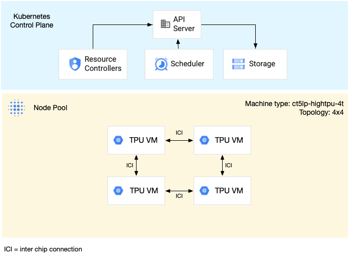
The following diagram shows a v5litepod-16 (v5e) multi-host TPU slice. This
TPU slice has four VMs. Each VM in the TPU slice has four TPU v5e chips
connected with high-speed interconnects (ICI), and each TPU v5e chip has one
TensorCore:
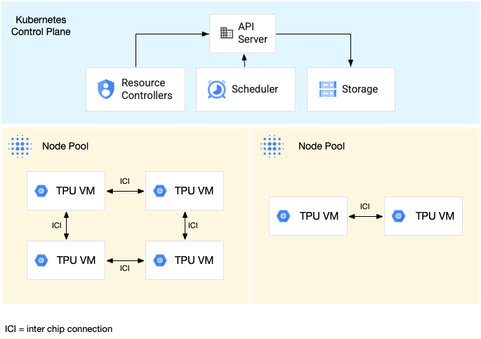
The following diagram shows a GKE cluster that contains one TPU
v5litepod-16 (v5e) TPU slice (topology: 4x4) and one TPU v5litepod-8 (v5e)
slice (topology: 2x4):
Single-host TPU slice node pools
A single-host slice node pool is a node pool that contains one or more independent TPU VMs. Each VM has a TPU device connected to it. While the VMs within a single-host slice node pool can communicate over the Data Center Network (DCN), the TPUs attached to the VMs are not interconnected.
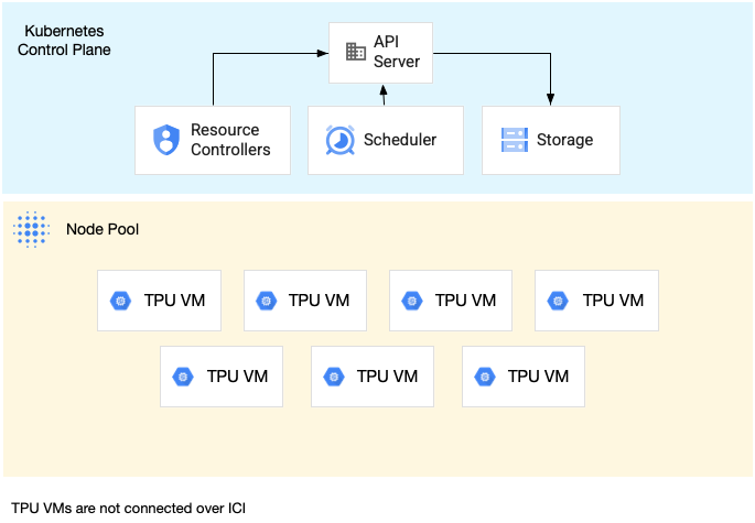
The following diagram shows an example of a single-host TPU slice that contains
seven v4-8 machines:
Characteristics of TPUs in GKE
TPUs have unique characteristics that require special planning and configuration.
TPU consumption
To optimize resource utilization and cost while balancing workload performance, GKE supports the following TPU consumption options:
- Flex-start: to provision Flex-start VMs for up to seven days, with GKE automatically allocating the hardware on a best-effort basis based on availability. For more information, see About GPU and TPU provisioning with flex-start provisioning mode.
- Spot VMs: to provision Spot VMs, you can get significant discounts, but Spot VMs can be preempted at any time, with a 30-second warning. For more information, see Spot VMs.
- Future reservation for up to 90 days (in calendar mode): to provision TPU resources for up to 90 days, for a specified time period. For more information, see Request TPUs with future reservation in calendar mode.
- TPU reservations: to request a future reservation for one year or longer.
To choose the consumption option that meets your workload requirements, see About accelerator consumption options for AI/ML workloads in GKE.
Before using TPUs in GKE, choose the consumption option that best fits your workload requirements.
Topology
The topology defines the physical arrangement of TPUs within a TPU slice. GKE provisions a TPU slice in two- or three-dimensional topologies, depending on the TPU version. You specify a topology as the number of TPU chips in each dimension as follows:
For TPU v4, v5p, and Ironwood (TPU7x) (Preview) scheduled in multi-host TPU slice node pools, you define the
topology in 3-tuples ({A}x{B}x{C}), for example 4x4x4. The product of
{A}x{B}x{C} defines the number of TPU chips in the node pool. For example, you
can define small topologies that have fewer than 64 TPU chips with topology
forms such as 2x2x2, 2x2x4, or 2x4x4. If you use larger topologies that
have more than 64 TPU chips, the values you assign to {A}, {B}, and {C} must
meet the following conditions:
- {A}, {B}, and {C} must be multiples of four.
- The largest topology supported for v4 is
12x16x16and v5p is16x16x24. - The assigned values must keep the A ≤ B ≤ C
pattern. For example,
4x4x8or8x8x8.
Machine type
Machine types that support TPU resources follow a naming convention that
includes the TPU version and the number of TPU chips per node slice, such as
ct<version>-hightpu-<node-chip-count>t. For example, the machine type
tpu7x-standard-4t supports Ironwood (TPU7x) and contains four TPU chips.
Privileged mode
If you use GKE versions earlier than 1.28, you must configure
your containers with special capabilities to access TPUs. In Standard
mode clusters, you can use privileged mode to grant this access. Privileged mode
overrides many of the other security settings in the securityContext. For
details, see Run containers without privileged mode.
Versions 1.28 and later don't require privileged mode or special capabilities.
How TPUs in GKE work
Kubernetes resource management and prioritization treat VMs on TPUs the same as
other VM types. To request TPU chips, use the resource name google.com/tpu:
resources:
  requests:
    google.com/tpu: 4
  limits:
    google.com/tpu: 4
When using TPUs in GKE, consider the following TPU characteristics:
- A VM can access up to 8 TPU chips.
- A TPU slice contains a fixed number of TPU chips, with the number depending on the TPU machine type that you choose.
- The number of requested
google.com/tpumust be equal to the total number of available TPU chips on the TPU slice node. Any container in a GKE Pod that requests TPUs must consume all the TPU chips in the node. Otherwise, your Deployment fails because GKE can't partially consume TPU resources. Consider the following scenarios:- The machine type
ct5lp-hightpu-4twith a2x4topology contains two TPU slice nodes with four TPU chips each, for a total of eight TPU chips. With this machine type, you: - Can't deploy a GKE Pod that requires eight TPU chips on the nodes in this node pool.
- Can deploy two Pods that require four TPU chips each, each Pod on one of the two nodes in this node pool.
- TPU v5e with topology 4x4 has 16 TPU chips in four nodes. The GKE Autopilot workload that selects this configuration must request four TPU chips in each replica, for one to four replicas.
- The machine type
- In Standard clusters, multiple Kubernetes Pods can be scheduled on a VM, but only one container in each Pod can access the TPU chips.
- To create kube-system Pods, such as kube-dns, each Standard cluster must have at least one non-TPU slice node pool.
- By default, TPU slice nodes have the
google.com/tputaint which prevents non-TPU workloads from being scheduled on the TPU slice nodes. Workloads that don't use TPUs are run on non-TPU nodes, freeing up compute on TPU slice nodes for code that uses TPUs. Note that the taint does not guarantee that TPU resources are fully utilized. - GKE collects the logs emitted by containers running on TPU slice nodes. To learn more, see Logging.
- TPU utilization metrics, such as runtime performance, are available in Cloud Monitoring. To learn more, see Observability and metrics.
- You can sandbox your TPU workloads with GKE Sandbox. GKE Sandbox works with TPU models v4 and later. To learn more, see GKE Sandbox.
Node pool auto-creation with TPUs
Node pool auto-creation supports the following Cloud TPUs only in specific GKE versions:
- TPU v3: 1.31.0 and later.
- TPU v5 and TPU v4: 1.29.0 and later.
- TPU Trillium: 1.31.1-gke.1146000 and later.
- Ironwood (TPU7x) (Preview): 1.34.1-gke.2541000 or later.
Other Cloud TPU types are supported in all GKE versions.
Cloud TPU node pool autoscaling
GKE scales automatically created or manually created Cloud TPU node pools that use the cluster autoscaler in one of the following ways:
- Single-host TPU slice node pool: GKE adds or removes TPU
nodes in the existing node pool. The node pool might contain any number of TPU
nodes between zero and the maximum size of the node pool as determined by
the
--max-nodesand the--total-max-nodesautoscaling flags. All of the TPU nodes in the node pool have the same machine type and topology. For more information about how to create a single-host TPU slice node pool, see Create a single-host TPU slice node pool. - Multi-host TPU slice node pool: GKE atomically scales up
the node pool from zero to the number of nodes required to satisfy the TPU
topology. For example, with a TPU node pool that has the
ct5lp-hightpu-4tmachine type and a topology of16x16, the node pool always has either 64 nodes or zero nodes. GKE scales the node pool down if there are no TPU workloads in the node pool. To scale the node pool down, GKE evicts all scheduled Pods and removes all of the nodes in the node pool. For more information about how to create a multi-host TPU slice node pool, see Create a multi-host TPU slice node pool.
Workload policy
Workload policy is only supported for Ironwood (TPU7x).
A workload policy is a type of resource policy that lets you configure the physical placement of the underlying infrastructure. A workload policy provides hierarchical configuration options for more fine-grained control.
Ironwood (TPU7x) supports the High throughput workload policy. This policy lets you do the following:
- Run distributed workloads that require high throughput, such as High Performance Computing (HPC) or machine learning (ML) training. The underlying infrastructure is configured to colocate the TPU VMs to reduce the network latency between the VMs.
- Define the maintenance strategy for TPU VMs to minimize workload disruptions.
Collection scheduling
Collection scheduling is only supported for TPU Trillium.
In TPU Trillium, you can use collection scheduling to group TPU slice nodes. Grouping these TPU slice nodes makes it easier to adjust the number of replicas to meet the workload demand. Google Cloud controls software updates to ensure that sufficient slices within the collection are always available to serve traffic.
TPU Trillium supports collection scheduling for single-host and multi-host node pools that run inference workloads. The following describes how collection scheduling behavior depends on the type of TPU slice that you use:
- Multi-host TPU slice: GKE groups multi-host TPU slices to form a collection. Each GKE node pool is a replica within this collection. To define a collection, create a multi-host TPU slice and assign a unique name to the collection. To add more TPU slices to the collection, create another multi-host TPU slice node pool with the same collection name and workload type.
- Single-host TPU slice: GKE considers the entire single-host TPU slice node pool as a collection. To add more TPU slices to the collection, you can resize the single-host TPU slice node pool.
Collection scheduling has the following limitations:
- You can only schedule collections for TPU Trillium.
- You can define collections only during node pool creation.
- Spot VMs are not supported.
- Collections that contain multi-host TPU slice node pools must use the same machine type, topology, and version for all node pools within the collection.
You can configure collection scheduling in the following scenarios:
- When creating a TPU slice node pool in GKE Standard
- When deploying workloads on GKE Autopilot
- When creating a cluster that enables node auto-provisioning
What's next
To learn how to set up Cloud TPU in GKE, see the following pages:
- Plan TPUs in GKE to start your TPU setup
- Deploy TPU workloads in GKE Autopilot
- Deploy TPU workloads in GKE Standard
- Learn about best practices for using Cloud TPU for your ML tasks
- Video: Build large-scale machine learning on Cloud TPU with GKE
- Serve Large Language Models with KubeRay on TPUs
- Learn about Sandboxing GPU workloads with GKE Sandbox